|
|
101 Forward Control Land Rover pages
LPG installation
Having fitted the replacement
engine, the vehicle was so much better that we decided
we'd like to use it more. However, it's a very expensible
vehicle to run, and really LPG is the only sensible way
forward. We did a lot of research on the various options,
and it soon became clear that Tinley
Tech are really good, so we got the kit
from them.
Tinley Tech's helpfulness during the
conversion was fantastic - they come back with answers to
e-mail questions straight away and if you get in a muddle
they will talk you through the problem on the phone, and
they are knowledgable people, too - we can thoroughly
recommend them. Also, if you need further supplies, their
on-line shop turnaround time is fantastic!
Once the conversion is finished, it
needs to be certificated to LPGA CoP11. CLS Dual
Fuels in Durham did that for us. They
were really helpful, too - offering advice before the
actual certification inspection which saved a lot of
hassle, and the registering it on the LPGA website. Again
we can thoroughly recommend these guys.
The pictures and words below
chronicle the story!
What the manual doesn't tell
you:
The cradle needs to be
adapted if you undersling the tank because there
needs to be a minimum of three straps when
underslinging and the middle one comes right
where the box is. Tinley Tech advised that with a
large tank, four straps are better. You have to
drill new holes in the cradle for the two middle
ones. The strap supplied for the middle has to be
drilled at the end and bolted into a new hole at
the back of the cradle and fitted in the standard
way at the front in another new hole. They also
supply a fourth strap which is fixed in the same
way. (See below for pic, but see the note about
the way the strap needs to be fastened.)
Assemble the cradle and tank
on the bench and pre-stretch the straps before
trying to do it under the vehicle. I had the warm
them (to expand them a little) first, too,
because it is sub-zero here at the moment. Once
you stretch them by tightening them (I left them
overnight), you can then take the tank off, mount
the cradle and them re-mount the tank relatively
easily.
Knock up a cradle for your
trolley jack so that you can use it to jack the
tank in to position. This is especially important
if you're working on your own (Lois has far too
much sense to go out in the cold!) The tank is
heavy, very ungainly and needs to be positioned
accurately.
Because the petrol system is
recirculating, the petrol pump runs continuously.
However, part of the modification is to fit a
solenoid valve in the main petrol line. I didn't
think it would be a good idea to have it running
against the solenoid (actually, no need for it to
be running anyway), and Tinley Tech advised
fitting the relay to switch it off when running
on LPG. The LPG/Petrol changeover switch isn't
really up to switching a big load like the petrol
pump.
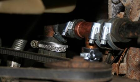
The water T-pieces provided
don't fit the 101 heater pipes. The ones provided
are too small. However 22mmx15x22mm copper
plumbing T-pieces with short legths of copper
pipe soldered in make ideal alternatives. I also
fitted a bleed valve so that the vapouriser
didn't end up with an airlock.
Running the sensor wire to
the coil negative didn't work for me - the gas
stayed on even with the engine stopped (which it
shouldn't). However, a quick phone call to Tinley
Tech came up with the suggestion of wrapping the
sensor wire round the coil HT lead - which works
a treat!
The stages of the
installation:
Preparation
|
 |
 |
 |
 |
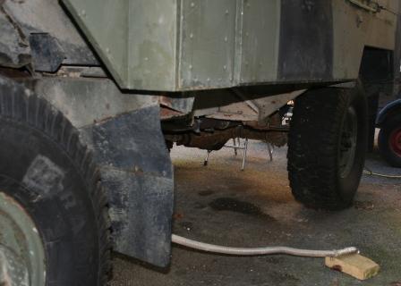
| First job was to remove the
battery box. The LPG tank will be fitted in its
place. I has already removed the air tank which
normally goes behind the battery box. |
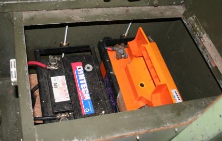
This is the new position for
both batteries - just behind the driver's seat.
It's very handy for the alternator, so cable runs
are very much shorter. |
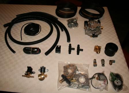
This is the complete kit
(except tank and cradle) from Tinley Tech. They
include pretty well everything, except basic
stuff like nuts and bolts to fit the cradle, and
wire. |
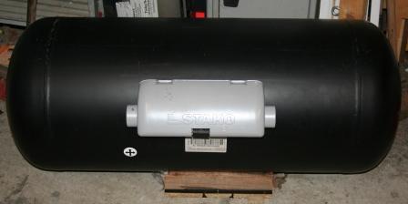
This is the tank. 110 litre,
four hole. |
|
|
|
|
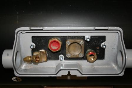
| And this is the business end
of the tank, with the unions for filling and
supply, the level unit and safety valve |
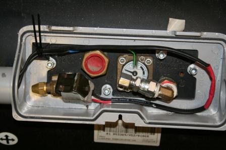
Here are the main
connections to the tank. The gas connections (on
the left is the take-off and on the right the
filler) and the electrical ones too (the lpg
cutoff solenoid on the take-off and the level
gauge). |
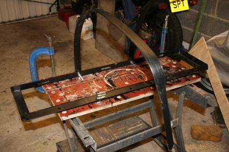
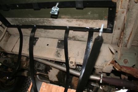
These are the alterations
necessary for an underslung tank - the two straps
are fitted to the cradle (see above) |
|
Installation
|
|
|
|
 |
 |
 |
 |
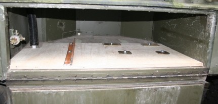
| This is the cradle in
position, located where the battery box used to
be... |
...and here are the load
spreading plates and board. It's not clear from
this pic, but the floor is reinforced with
3/4" exterior ply, then the spreader plates
are on top of that. I used angle iron as the
spreader on the left-most bolts so that I can put
in a locker divider later - the spare wheel is
destined for elsewhere anyway because it takes up
too much internal space. |
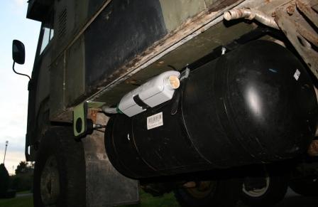
Here's the tank
installedwith the filler fitted and everything
tidied. You can see the Eberspacher heater exhust
re-routed and coming out to the rear of the LPG
tank. Note that the additional strap, fixed just
behind the grey box, if fitted wrongly - the
spare bit should run under the strap, not over it
at it's shown here - I had to change it. |
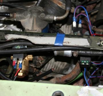
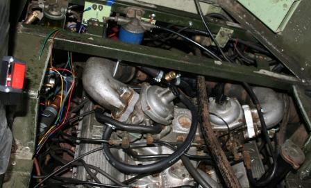
Here are the engine
compartment solenoid valves and the relay. The
LPG solenoid valve is bottom left of the picture,
and the petrol solenoid is at the top right,
beside the fuel filter and plumbed between the
sediment bowl (which isn't in the pic) and the
filter. At the bottom right of the picture is the
extra relay that controls the petrol solenoid and
the petrol pump. |
|
|
|
 |
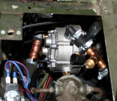
Here's the vapouriser,
plumbed in to the water system. The copper thing
to the right of the picture, above the
vapouriser, is an air bleed valve - not included
in the kit -but the place I put it is high and
therefore begs for an airlock! Below the
vapouriser you can just see the copper T-piece
fitted to the heater pipe, providing hot water
in.
|
And here is the T-piece
plumping the vapouriser in to the heater return
pipe. This is near the bottom radiator hose. |
The mixers are fitted here,
and you can just see the power valve and its
T-piece. |
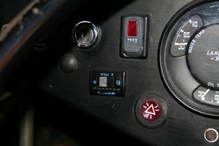
Here's the changeover switch
- it fits nicely in to this gap. |
 |
|
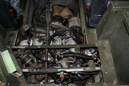
And here's the finished job.
|
|
|